Like the dual VR board V2.0 that it replaces, this is a small board with surface mount components that is sold fully assembled. It has two VR differential inputs, two 0-5V square wave outputs, and the power supply connections (ground and either 5V or 12V depending on the version). The V2.1 board still has the same circuit as the V2.0 but has a new form factor. It is smaller and the pads are placed such that they fit a DIP8 pattern. So you can use a DIP8 socket or solder it directly to a proto area or a perforated board. It still has the two mounting holes so you can still solder wires directly to the board.
It also now comes in two versions: the internal and the external versions. The internal version is for those who want to use it in the ECU case and it doesn't have the on-board voltage regulator and needs to be powered by a 5V source. The external version has an on-board voltage regulator and can therefore be powered by a 12V source from the car. However you still need to put it in some sort of enclosure to protect it from the environment.
The thread discussing the board can be found here.
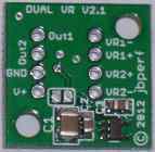
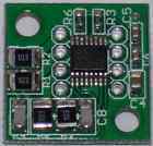
This is the fully populated board. You can see the power supply circuit on the bottom which is populated for the external version; this is not populated for the internal version. The 2 mounting holes can be used to mount the board inside the ECU case or any other case when used outside the ECU.
The solder pads on each side of the board are for connecting wires or pin headers. The bottom also has labels for each pad to indicate its function. The V+ pad is for either 5V or 12V depending if the board is an internal version (5V) or an external version (12V) and GND is used to connect the board to the power supply ground. The VR1+ and VR1- pads are used to connect the first VR sensor and the Out1 pad is the 0-5V square wave signal generated from the input. The VR2+ and VR2- pads are used to connect the second VR sensor and the Out2 pad is the 0-5V square wave signal generated from the input.
Note that the 12V connection for the external version can be to any supply that provides more than about 5.5V.
The board can also be used with Hall or opto sensors. In that case, the sensor is connected to VR+ only and VR- is left floating (not connected to anything). If the sensor does not generate a voltage (open drain output), a pull up resistor will be needed. The board can be used with either a 5V or a 12V input signal regardless of whether the board is an internal or external version.
")
")